


|
|
slide No. 9 / 12
|
|
|
|
slide No. 9 / 12
Well then, results of the program are shown from now on. All of the results assume Copper as a target material, and Argon as the sputtering gas.
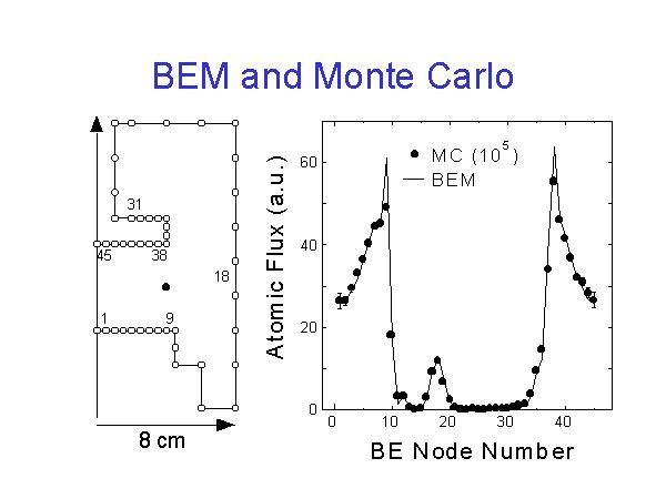
The left figure shows the model of chamber boundary. As I said before, it is axisymmetric, and THIS is the symmetric axis. It is split to elements, from 1 to 45.
It is based on our actual sputtering chamber. Target is placed THIS face, and substrate is placed HERE.
At first, conventional MC method is compared with new BEM approach. We put here the particle source, well, the thermalization point, and checked the flux on each boundary element.
Monte Carlo Method is performed for 10 to 5 of particles, assuming the pressure of 10 Pa. The results are put in right figure with marks. Here is some error bars, near the axis and actual area is small.
BEM result is presented with this line, which agrees fairly well with the Monte Carlo results. There is some difference at the nearest nodes, HERE and HERE, it may be originated from the constant node modeling of the BEM. The effect of the source term is counted at the center of each node, so at the nearest one, it does not always represent the average on the whole boundary.
The computation time needed to obtain the MC results is about 14 hours with our environment. On the other hand, BEM result is obtained within a few minutes, even we repeat the summation of source term for 10^5 times.